

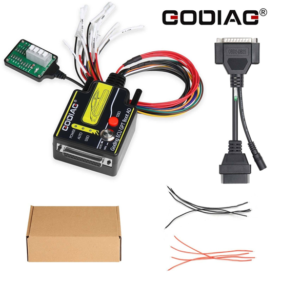


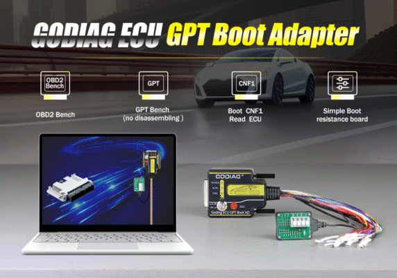
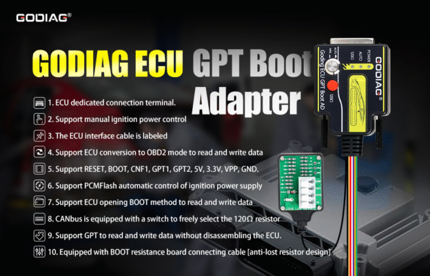
The GODIAG ECU GPT Boot Adapter is a specialized hardware tool designed to help automotive technicians read and write ECU (Engine Control Unit) data. It allows you to work via OBD2 Bench or GPT Bench methods without opening the physical ECU casing, minimizing the risk of hardware damage.
Because your request lists the product’s primary capabilities, the exact setup and workflow will depend on whether you are doing a standard Bench read or using the advanced GPT (General Purpose Timer) boot method for password-protected ECUs.
Below is an overview of how this adapter operates across different technical scenarios, using J2534 passthru devices.
Scenario 1: Standard OBD2 Bench Mode (No Disassembly)
This setup is used for standard ECUs that allow data reading and writing directly through the diagnostic lines without needing security password extraction.
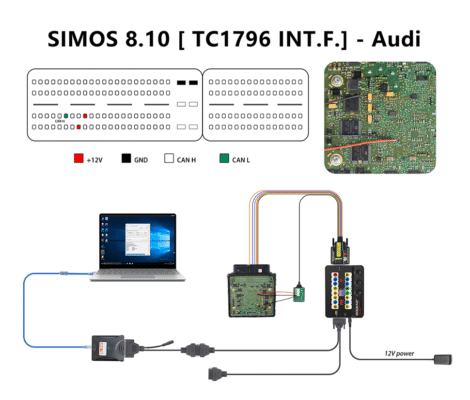
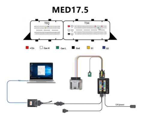
- Connection Layout: Connect the J2534 device to your PC. Plug the J2534 device into the GODIAG Adapter’s OBD2 female port. Connect the adapter’s specialized DB15 cable directly to the ECU pins (Power, Ground, CAN-High, CAN-Low, or K-Line).
- Power Control: Use the manual or automatic power switches on the GODIAG adapter to cycle the ignition (IGN) power. This mimics turning a car key on and off, which is required by tuning software to initialize communication.
- Execution: Open your chosen tuning software (e.g., PCMTuner, PCMFlash, BitBox). Select the corresponding OBD2/Bench module, and perform the read/write operation.
Scenario 2: GPT Bench Mode (No Disassembly with Password Extraction)
This setup is required for modern, highly secure ECUs (such as Bosch EDC17, MED17, or MEVD17) where the tuning software needs to bypass anti-tuning protection by reading a security password via hardware timers.
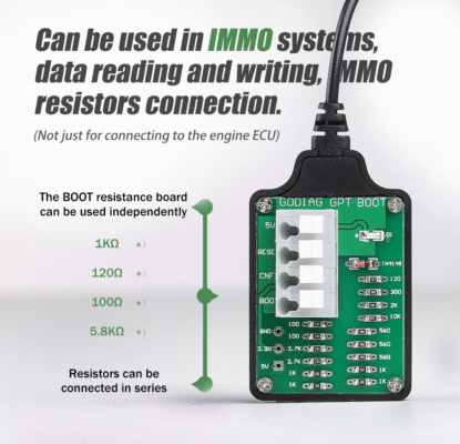
- Connection Layout: Follow the same steps as the standard bench setup, but connect two additional specific wires from the GODIAG DB15 cable: GPT1 and GPT2.
- Pinout Dependency: You must look up the exact wiring diagram for your specific ECU model to locate the precise GPT digital signal pins.
- Execution: The software will issue a command through the J2534 device to send high-frequency clock signals over the GPT lines. The GODIAG adapter stabilizes these signals, allowing the software to read the chip password, unlock the flash memory, and safely read or write the data clone.
Compatible J2534 Hardware & Software Environments
The GODIAG adapter acts as a bridge; it does not read data on its own. It relies on your existing tools:
- Supported J2534 Devices: Tactrix Openport 2.0, Scanmatik 2 Pro (SM2), Mongoose J2534, or standard pass-thru devices from Autel, Launch, or VXDIAG.ISSBD J2534 Made in Bangladesh
- Supported Software: PCMFlash (frequently paired with this adapter for modules 53/71), PCMTuner, BitBox, Foxflash, or Alexflash.
Key Operational Tips
- Voltage Stability: Always connect a stable 12V external power supply to the GODIAG adapter. Fluctuations during writing can brick the ECU.
- Color-Coded Wiring: Double-check the standard color codes on the DB15 cable (Red = +12V, Black = GND, Blue = CAN-H, Yellow = CAN-L). Incorrect pin insertion can permanently short-circuit the ECU mainboard.
To help give you the exact wiring diagram or step-by-step instructions for your project, please share a few more details:
- What is the specific ECU make and model you are trying to read? (e.g., Bosch EDC17C60, Continental SIMOS18)
- Which J2534 device and tuning software are you planning to use with the adapter?
- What is your ultimate goal for this ECU? (e.g., cloning a damaged unit, chip tuning, or turning off specific fault codes)


Reviews
There are no reviews yet.